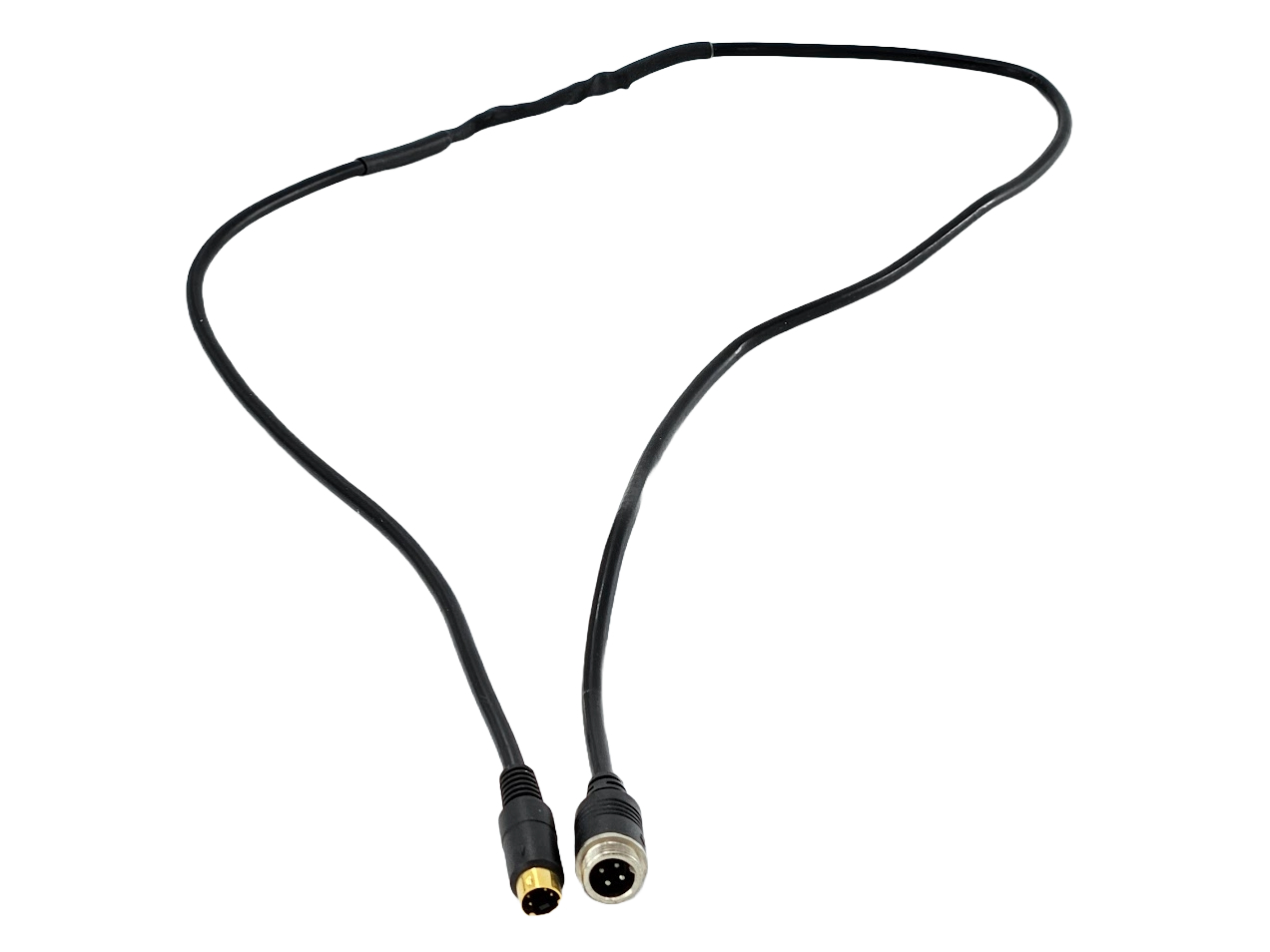
Creating adaptors for a reversing camera
With more vehicles having a reversing camera fitted as standard we are seeing more and more people needing to replace these when they fail. If you have a 360 degree system or one built into a car then there are issues with replacing an existing factory fitted camera. The biggest issue is many of the cameras use a 5 volt power source whereas aftermarket units are 12 volt. If yours is on a Lorry, motorhome or is an aftermarket product then these instructions should help you convert your existing connector to the 4 pin aviation that is so common.
Before you start it is worth checking with us as we stock a number of adaptors to match common systems used in UK vehicles.
Step 1
This is where you check your existing camera cable to see what cores are contained within it. It can be helpful not to cut the cable completely, but to open it up by carefully splitting the cable insulation. What you find inside can vary from 2 wires and a bare outer shield upwards to 7 or 8 wires. Generally you would hope to expect them to have follow a colour code as follows:-
Red = 12v
Black/bare wire = negative
Yellow = video
White = sound
What you expect and what they actually are is another matter!
You may find that one of the wires carries 12 volts to power the IR LEDs in the camera. Another may be used to carry 12 volts to power a small heater, although this is fairly rare in reversing cameras in the UK. I have seen white used as the earth or as the video channel.
Another potential problem is where there is a wire within an wire.

This picture shows the wiring from an Obserview camera. If you look carefully at the white wire you can see there is an inner insulated wire with an outer shield all within an outer insulation. If you miss that then you will ground the video signal so it will not work. On this camera just connecting the 3 wires labelled will produce a picture. You can usually identify a wire within a wire as it is thicker than other wires in the cable.
If yours is a very small camera then you sometimes find a small plastic block about 12 inches from the camera body. This houses a small power regulator that drops the voltage down to 5v. If you include this in your adaptor a 12v camera will not work so it needs leaving out.
Step 2
By now you should have some idea if you can identify what each cable in your wire does. The video will almost always have a shield around it. The 12v can be identified with a multimeter. The bare shield is the negative and you often find one of the other cores is also negative. A continuity check should identify this.
The next step is to cut off the plug of your failed camera with a good length of cable to help create the adaptor. On one of our 1m 4 pin extension cables cut in half to give you the male connector. You are now going to join your connector of your camera to the male connector from our cable.
.jpg)
On this one we have combined the black earth wire and bare shield together. We did not use heat shrink on this. You can often get away with cutting the bare shield back and connecting only the black wires. Our fitters often do this if they want to shorten one of our 4 pin extension cables. The other wires are soldered together and heat shrunk using a hot air gun to shrink the tubing. On this you can see we joined yellow to yellow and red to red as both sides used that convention for positive and video. The sound though was on a different colour core compared to our cables which is why the white goes to a different colour. The lead we were soldering our wire onto had another wire we just blanked off with heat shrink. The whole joint then was covered in heat shrink to protect it.

The photograph above shows a typical finished adaptor. Veba is a brand that appears to be discontinued, but has numerous systems available on eBay and Amazon. We get a lot of people phone up about them so we have reservations about their quality.

The adaptor cable then just needs checking against the pin diagrams above. The 12V is the important one as get that wrong and you can damage the camera or monitor or both. When you have finished the adaptor can then be used to plug into your existing wiring without having to damage it. It will then allow you to change the camera whenever you need to easily as the 4 pin aviation connector is very common. In theory you should have a working camera system. If not then the first place to start is checking continuity down cables. Every year we see a couple of cases where cables have been damaged by either animals or fitters installing other equipment.
If you use a multimeter to check continuity along a cable then make sure there is no camera or monitor attached. The meter applies a voltage of 9v and this can be enough to damage sensitive electronics.